- Published on
Experiments in combustion in grad school
- Authors
- Name
- Ali Tarraf
- @alitarraf


I started my research at the Combustion and Propulsion Research Lab in Indiana University Purdue University under the supervision of Dr Razi Nalim in the beginning of 2015. The next 2 years that followed were a tremendous learning experience. I had been away from academia for 5 years and diving back into textbooks and theories was not easy, however I found a fulfilling challenge in experimental research in the lab like with pulse jets, flame throwers, wave rotors, combustion chambers and much more. What follows is a distillation of my technical work in those two years and some of the lessons learned along the way.
Introduction
Pressure wave machines can be traced to 1928 when Burghard patented a cell rotor device. So what is a pressure wave machine? It is a device that harness shock waves to increase pressure in a closed volume chamber. A compressible fluid entering the cell compresses the column of fluid in the cell through a pressure wave. Several elongated cells arranged on a rotating wheel are opened and closed at a precise timing allowing the compression and discharge cycle to fully complete in one rotation of the wheel. Pressure wave machines, also known as wave rotors have seen applications in automotive as a replacement for turbochargers like the compress supercharger of Mazda, and in some applications are being considered to replace gas turbine combustors in aerospace and power generation (Nasa wave rotor).

Motivation
The main motivation driving close to a century of wave rotor combustion research efforts can be summarized in the four points below.
- Wave rotors machines have an improved thermodynamic efficiency due to higher pressure and temperature operation. In layman's terms this means more bang for your buck of fuel compared to traditional engines.
- Wave rotors machines produce less nitric oxides due to the short residence time of combustion gas in the channel. In layman's term this means cleaner, greener combustion compared to traditional engines.
- Wave rotors machines have self-cooling channels due the colder fuel air mixture entering the channel each cycle. This means they have less complicated cooling systems compared to traditional engines.
- Wave rotor machines have continuous and steady operations unlike other unsteady pulse detonation devices. This translated to simpler mechanical operations.
However two main challenges exists with wave rotors. The first challenge is sealing the combustion gases in the rotating channel between two fixed plates. And the other challenge is related to igniting the fuel mixture in the wave rotor channel.
Depending on applications, the rotor can be spinning up to tens of thousands of revolution per minutes. The goal of my research was to answer a fundamental question: how long does a fuel like methane takes to ignite in a wave rotor operations where a closed chamber is spinning at thousands of revolutions and at elevated temperature?
Now looking back in time, it seems surprising to spend so much effort and time trying to answer a simple question. But isn't that how progress is made,asking fundamental questions, and striving to come up with clear answers.
Experiment
An experiment was designed to simulate one channel of a wave rotor where a pre-chamber hot jet ignites the main mixture in the adjacent main combustion chamber. The goal of the experiment is to measure the time between the hot jet entering the main chamber and ignition in the main chamber. Consequently, this difference in time is known as ignition delay. Two ways are used to measure ignition delay: by recording pressure data using a dynamic pressure sensors, and by recording schlieren videos of the combustion with a high speed camera.
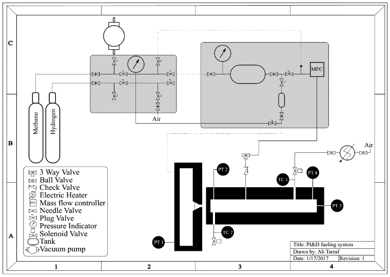
The set up of the experiment consists of two chambers that are filled with Methane and Hydrogen; a rotating chamber and a fixed chamber with optical access. Both chambers are instrumented with dynamic pressure sensors. Part of my work consisted of designing and fabricating the main combustion chamber, the fueling system, the ignition system, the heating system, the sealing system, and the chamber positioning system. A Piping and Instrumentation diagram depicting the set up is shown below.

Some of the highlights and features of the experiment set up:
Metal Fabrication
A stainless steel chamber made of 3 blocks sandwiching two optical quartz glass. Precision machining is expensive specially hard steels like SS304 so we did almost everything in house. Drilling vertical holes on a 16" tall piece isn't fun at all, it requires patience, and precision. And threading stainless steel is a slow delicate process, just take your time to avoid a bad day.
We use water jet cutting on the windows opening of the stainless steel blocks to save machining time, this worked perfectly on the big horizontal opening. However we had a rectangular opening to cut on the end of the middle block which caused some problems. We had to re-weld to fill the gaps cut by water abrasive, and then re-surface again. Use water jet cutting with caution.
Heating
Installing an electric heater to blow hot air and increase the temperature inside the chamber was a learning process. You need to size the heater to get adequate heating power to the hot air flowing into and out of the main chamber. Plus installing and programming PID controller was a must to be able to have a good amount of control over the desired air temperature.
Mass flow controller
I was so annoyed of continuously opening and closing valves to fuel the main chamber, that I decided to automate the process. Thinking outside the box, I decided to use a mass flow controller to deliver a fixed amount of fuel automatically. Mass flow controllers typically deliver a constant mass flow rate of fluids in a steady state situation.
However in my case I wanted a fixed amount of fuel delivered no more. So I had to develop a new time based model to shut off the mass flow controller once the adequate amount of fuel is reached in the main chamber. Things got interesting because I had to re-calibrate the mass flow rate controller using water displacement methods (a shout out to Archimedes!) in order to build the time dependent fueling models and control its start and stop time electronically with a digital signal from the computer.
Ignition automation
Having to manually press a button to ignite the fuel mixture for thousands of time during the lifetime of this experiment was an opportunity ripe for automation. I built an opto isolated circuit using opto relays to transmit the ignition signal to an ingnition coil. The ignition signal is computer generated from a National Instrument card controlled by the Labview software.
A combustion test sample
A typical combustion test shot in slow motion using a smartphone camera would look like this. https://youtu.be/Ot1ehs52Ic
Results
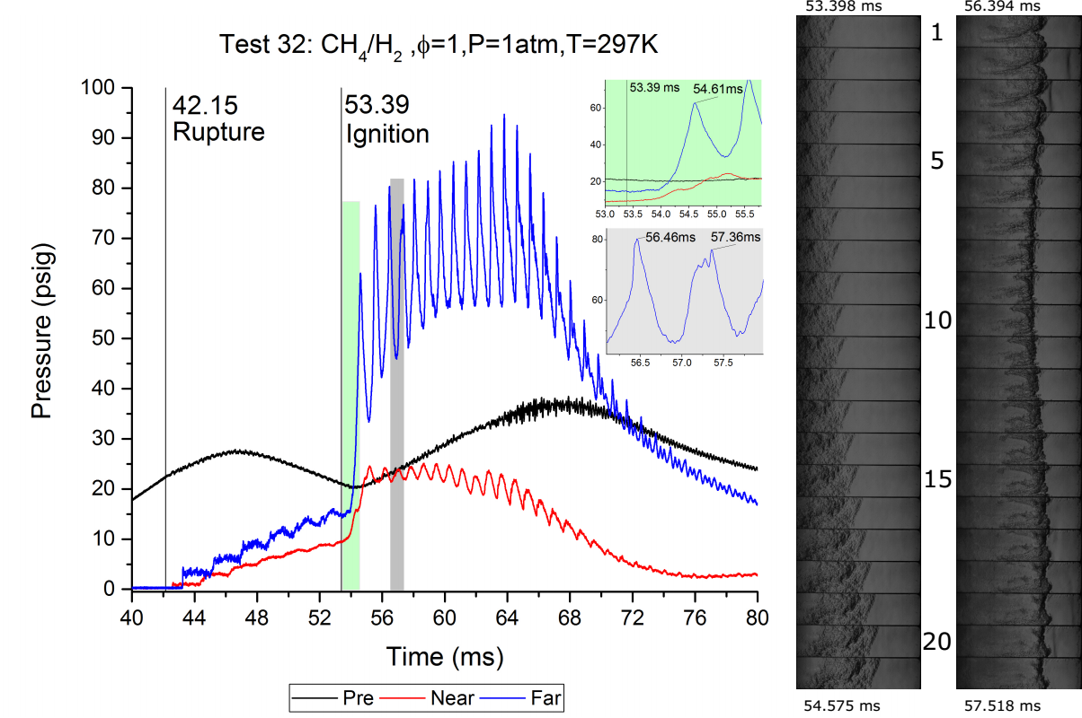
The figure below summarize two years of efforts. It takes 42.15 milliseconds from the computer generated ignition signal until the rotating pre-chamber combustion ruptures the aluminum foil separating the two combustion chambers. After rupture, the jet entering the main elongated chamber ignites the mixture at 53.39 milliseconds. So, the ignition delay from rupture to ignition in this specific case it the difference 11.24 milliseconds.
The tests were repeated for different fuel mixture and pre heated temperature. General relationships between the effect of different mixtures and temperatures on ignition delay were characterised. More details can be found in the thesis report which is openly accessible.

Schlieren videography of Hydrogen combustion from the front side of main chamber
Schlieren videography of Hydrogen combustion from the back side of main chamber
Schlieren videography of Methane & Hydrogen combustion from the front side of main chamber
Schlieren videography of Methane & Hydrogen combustion from the back side of main chamber
Tips and lessons from doing experiments
- It is really hard to create a good scientific, controlled experiment that answer a simple deep fundamental question. Nature has its own ways and your job as an experimenter is to discover its inner workings by taking a snapshot of life at the moment of your test, and zoom in with your sensors to reveal a nugget of information. It is hard, but keep chipping away with your mind axe.
- I spent 95% of my time building and designing the experiment, and 5% of the time to run it and get data. As an experimenter your constant and never ending improvement of your experiment needs to be moderated. There will come a point where you should stop making it better, and just make use of it. It took me a year plus to realize this. I delayed my graduation because I needed to make it better. Having come that far, I can surely improve it a bit more so it gets a little bit more perfect.
- The unexpected will happen, and delay all your plans. We had to move our lab twice during my work there; not fun at all! This violates the first rule an experimenter declares to the external world: don't touch my stuff!
- There is a constant tension and synergy between the experimenter and the theoretician. This relationship is super important in the progress of your experiment. You as an experimenter should seek to have this group dynamic between theoretical discussions about your experiment's implications and actually developing and running your tests. Besides it is always fun to make fun of Phds colleagues who spend 5 years building abstract mathematical and physical models, while you are doing the fun stuff in the lab.
- Take a fulfilling pride in the work that you do, even if compared to others you are doing "less" (not publishing in the best journals, not getting the regonition you deserve, being late in delivering etc...), ignore that and just focus on putting in your all, your best efforts. Strive for that level of flow where you are your experiment, and your experiment is you. This was the most valuable experience and lesson I gained while working in the lab.